Pages

Tampilkan postingan dengan label robot. Tampilkan semua postingan

Minggu, 08 Mei 2016

Using Arduino For Mind Control

This isnt a post about using a microcontroller (MCU) to control someones mind -- its a post about how to use an Arduino device that lets you use your brainwaves to manipulate inanimate objects.
OpenBCI prototype called "Frankenboard"

Heres how the August 11 article "Building Mind-Controlled Gadgets Just Got Easier" from IEEE.org explains this new brain-computer interface (BCI).
"Their system enables DIYers to use brain waves to control anything they can hack—a video game, a robot, you name it. “It feels like there’s going to be a surge,” says Russomanno. “The floodgates are about to open.” And since their technology is open source, the creators hope hackers will also help improve the BCI itself. Their OpenBCI system makes sense of an electroencephalograph (EEG), signal, a general measure of electrical activity in the brain captured via electrodes on the scalp. The fundamental hardware component is a relatively new chip from Texas Instruments, which takes in analog data from up to eight electrodes and converts it to a digital signal. Russomanno and Murphy used the chip and an Arduino board to create OpenBCI, which essentially amplifies the brain signal and sends it via Bluetooth to a computer for processing."
Current OpenBCI board
One nice aspect of Arduino is that its getting more and more people who arent electronics experts, computer programmers or engineers involved with physical computing. The IEEE article says they are "artists who met at Parsons the New School for Design." In the Humboldt Microcontrollers Group, there is a forester, a biologist, and an artist. And wed love to have more non-engineers and others whose main experience and training is not in the field of electronics. The Arduino movement seems to encourage a whole new spectrum of people to see how they can apply MCUs and other modern electronics to their particular field of interest.

I havent quite figured out if I think OpenBCI will be around for the foreseeable future. They seem relatively legitimate, but their website appears to be either very new or not a high priority for the founders of OpenBCI. Quite a few of the webpages on the site say Under Construction. Even the Getting Started page says its under construction. But IEEE is a pretty reputable organization, and I dont think theyd have published the article if they werent comfortable that the project was legitimate. Overall, though, it appears youll get the OpenBCI hardware if you want to spend the $399 on either the 8-bit or 32-bit board kits. They also have a GitHub site that contains "the core OpenBCI hardware and software frameworks."

In addition to the IEEE August 2014 article about OpenBCI, there were a number of articles in early 2014 when OpenBCI did a successful Kickstarter campaign, getting more than twice their original goal of $100,000. Wired did an article in January 2014 titled, "These Guys Are Creating a Brain Scanner You Can Print Out at Home." The article featured a 3D printed brain scanner headset that they called the Spider Claw 3000. Heres the articles description of the brain scanner:
"Spider Claw 3000" 3D printed brain scanner
"It includes sensors and a mini-computer that plugs into sensors on a black skull-grabbing piece of plastic called the “Spider Claw 3000,” which you print out on a 3-D printer. Put it all together, and it operates as a low-cost electroencephalography (EEG) brainwave scanner that connects to your PC...You can target up to 64 locations on the scalp with a maximum of 16 electrodes at a time."
The $399 starting price for the OpenBCI is too steep for my budget, but Im sure there will be some pretty interesting developments with this equipment in the next few years. The IEEE article mentions three projects:
"Audette, the engineer from Creare, is already hacking robotic “battle spiders” that are typically steered by remote control. Audette used an OpenBCI prototype to identify three distinct brain-wave patterns that he can reproduce at will, and he sent those signals to a battle spider to command it to turn left or right or to walk straight ahead. “The first time you get something to move with your brain, the satisfaction is pretty amazing,” Audette says...In Los Angeles, a group is using another prototype to give a paralyzed graffiti artist the ability to practice his craft
Chip Audette and brain-controlled Hex Bug battle spider (from IEEE)
again. The artist, Tempt One, was diagnosed with Lou Gehrig’s disease in 2003 and gradually progressed to the nightmarish “locked in” state. By 2010 he couldn’t move or speak and lay inert in a hospital bed—but with unimpaired consciousness, intellect, and creativity trapped inside his skull...They’re using OpenBCI to record the artist’s brain waves and are devising ways to use those brain waves to control the computer cursor so Tempt can sketch his designs on the screen...David Putrino, director of telemedicine and virtual rehabilitation at the Burke Rehabilitation Center, in White Plains, N.Y., says he’s comparing the open-source system to the $60,000 clinic-grade EEG devices he typically works with...Putrino hopes to use OpenBCI to build a low-cost EEG system that patients can take home from the hospital, and he imagines a host of applications. Stroke patients, for example, could use it to determine when their brains are most receptive to physical therapy, and Parkinson’s patients could use it to find the optimal time to take their medications
."
I wonder what some imaginative teenagers who have a lot of time and energy on their hands will come up when they start hacking OpenBCI...

**********
Read More..

Sabtu, 09 April 2016

Make Your Android Phone A Programmable Robot

If youve got a recent Android phone with modern sensors, a current Kickstarter project aims to turn that phone into a programmable robot.
Hippo-ADK basic board

The Hippo-ADK (Android Development Kit?) is profiled on Tech In Asia in the article, "This startup turns your Android phone into a fully programmable robot." While previous coverage of the Hippo-ADK, such as this Hack A Day post, focused mainly on the self-balancing capability of a two-wheeled robot made with Hippo-ADK and a gyroscope-equipped Android phone, the Tech In Asia article makes it clear the concept is to make good use of whatever sensors are in the phone.
"The mass adoption of Arduino opened up hardware prototyping to the world, serving as a common platform and large community for millions of hobbyists and professionals. But even though an Arduino board only costs about US$25, finding and purchasing many of the other components can be time consuming and expensive. That’s why Shenzhen-based Hippo Devices is developing a new, easier to use controller board called Hippo-ADK. The device plugs into a user’s Android phone, allowing it to utilize the phone’s proximity sensor, gyroscope, Bluetooth, camera, and other features. “Everyone has a mobile phone, why not make use of it? Why not make use of these $300 worth of sensors that everyone already has?” says Hippo’s
Hippo-LEGO shield
marketing coordinator...Besides saving money on sensors, Hippo-ADK doesn’t require learning a new programming language like Arduino. Hippo offers a graphical drag-and-drop programming environment...the Java API...If you’re an Arduino junkie and you prefer to stick to your guns but would still like an easy way to take advantage of your phone hardware, it’s compatible with Arduino hardware and software...It comes equipped with several extra sensors baked into the board, including infrared, which can control home appliances like air conditioners and thermostats
..."
Hippo-Arduino shield
As mentioned in the article above, you can put your Arduino knowledge to good use with the Hippo-ADK, but you might also feel compelled to expand into some App Inventor or Java programming if you pick up some of the Hippo hardware. Arduino seems almost to be used by Hippo as a marketing tool, saying that they are "combining an Arduino-like microcontroller board with Android." Their board uses an STMicroelectronics microcontroller, not an Atmel MCU. The Arduino hardware Hippo is providing at this point is the Hippo-Arduino, a shield that connects Hippo-ADK and Arduino (see picture at right).
Instructables Hippo

The Kickstarter original funding goal of $10,000 has been met, but this isnt one of the viral crowdfunding projects at this point. With 14 days left, the total raised as of the evening of August 14 is $16,457. One aspect that may have caused some people to hold off on supporting the campaign is that building a self-balancing two-wheeled robot will cost significantly more than the $39 (early bird) or $49 for the Hippo-ADK. It looks like it would end up being a couple hundred dollars for all the parts for a self-balancing robot, assuming youre starting with an Android phone that has a gyroscope you can use for robot balance control. If youre interested in building that self-balancing robot, Hippo posted an Instructables for that.

Heres a bit of what the Kickstarter page says about the Hippo-ADK:
"Hippo-ADK connects with your Android devices in real time through USB and Bluetooth.This allows you instant access to sensors,switches, accelerometers, gyroscopes, magnetometers, communication modules (Wi-Fi, GPS, GSM), cameras, and LCD screens without even having to spend a dollar on optional parts. It is all on your Android devices...If you want to expand the capabilities of our firmware you can use Arduino language and IDE to program Hippo-ADK...For beginners, use the graphical programming platform App Inventor to create your first “Hello World” Hippo-ADK project in less than 10 minutes. For the more experienced, enjoy the variety of high-level customization available by our Java API...For those who want to make even cooler stuff with Hippo-ADK such as robots and intelligent homes, we provide expansion boards and modules to facilitate more rapid development."
I like the concept of using the power and features of a smartphone to help power a robot. And the Hippo is certainly not the first -- there are other robots powered or enhanced with smartphones, including Romo and SmartBot. The Wall Street Journal (WSJ) even had a January 2014 article titled "Smartphone Robots Could Be About to Invade Our Homes." The real question is what the killer app will be for phone-carrying robots. Part of the challenge for mass production is the huge array of phone sensors, features, processors and operating system versions on the billions of cell phones being used around the world. Connecting your phone to your robot will be commonplace when it has clear benefits, as opposed to doing it because you can. As the head of iRobot Corp. said in the WSJ article,
Hippo non-balancing robot
"...the challenge is to meaningfully integrate a mobile device and a robot. "Are you connected because of a fad or because the customer experience is greatly enhanced by the addition of this technology?"
Im looking forward to the first phone-bot that figures out the answer to this question. Not only will our robots be able to do more and be more interesting, Im betting our phones will see new innovations, sensors and capabilities if theyre frequently used to enhance our personal robots.

**********
Read More..

Minggu, 03 April 2016

Welcome To Humboldt Laser Harp In Detail

[Tonights post is by Ed Smith, participant in the Humboldt Microcontrollers Group.]

In this post well go through the Humboldt Makers Groups Humboldt Laser Harp (HLH) in rather more detail than we have previously.

If youre not familiar with the concept of a laser harp YouTube has plenty of videos of different styles, or of course you can keep reading and get familiar that way. This is our harp:


We opted for a closed-frame harp rather than an open frame, as the closed frame struck us as an easier proposition. It also gives us control over the laser path, rather than letting it head off into the ether. Important for harps that will be played outdoors (as ours is) or near airports / airplane flight paths.

For lasers we opted for super cheap laser pointers from the local dollar store; at a buck per laser this beat mainstream suppliers prices by a huge margin.
Mounting the whole laser would be difficult, and those batteries dont last very long, so Nick ripped them open and hacked away most of the PCB, leaving us with a much more manageable package.
Those of you familiar with LEDs / laser diodes and button cell batteries may be able to guess what happened next.
We read the battery spec, 1.5v each, and fed the lasers ~4.5v. What we failed to consider was the internal resistance and resulting voltage drop of the button cell batteries.

The lasers looked amazing, for about half an hour.
Then they started to burn out. Oops.

After replacing the dead and dying lasers Nick did more testing and we eventually solved this by running the lasers on 3.3 volts, which seems to work well. Unfortunately more lasers were damaged during testing and we ran out of time to replace them, resulting in a few "strings" that didnt work well in direct sunlight. Oh well.
We are debating different methods of laser amperage control for future harp designs.
To hold the Lasers Nick designed and 3D printed some lovely adjustable mounts for them.

The corks hold the top end of a spring, which pushes the mounts against their legs (screws) and against the harp frame. By turning the screws the aim of the laser is easily adjustable. I failed to take a picture of a mount up close, but you can see the general idea.

On the bottom side each laser hits a light sensitive resistor (LDR) light sensor, each sensor has a 3D printed holder and light guide tube.

The black heatshrink around the tube helps block out ambient light and results in a stronger signal from the laser. This turned out to be crucial when operating the harp in daylight outdoors.

To convince the harp to stand upright we turned to Gordon, who hit the scrap yard and attacked what he found with his MIG welder. The result was a very stable base that complimented Nicks choice of an industrial theme wonderfully.
The rear screen is held in place by a pair of wing nuts, allowing us easy access to the center area. This center area will eventually hold the electronics package as well as some light effects.

The combination of mild steel base and aluminum body gives the harp a very low center of gravity and makes it quite stable. I was very happy about this when sitting behind it at the recent maker fair, as the road had a fair crown to it and we had the harp on a card cable. If it was inclined to tip it would have been a very nervous time for me!

To finish off the hardware side of the harp, heres a view from the rear.

I was in charge of the electronics package for the harp, I used a Texas Instruments Stellaris Launchpad microcontroller board for the brains. The primary reason I chose that board is that it has 12 analog inputs, making the job of reading 12 LDRs much easier. This project could be done with a microcontroller with fewer analog inputs, but you would need to use an external ADC or some comparators to turn the analog voltage from the LDRs into a digital signal.
To the right you can see the finished, prototype, electronics package. I used some perfboard to make a BoosterPack (what TI calls expansion boards, Arduino calls them Shields) for the LaunchPad. This simplified my design somewhat and made it easy to swap a new MCU into place if I accidentally blew this one up. Thankfully I didnt, but it was nice to have the option anyway.

Most of the board consists of 12 copies of a very simple circuit. The 15 pin connector has one pin for positive voltage to the lasers, one ground pin, one "feature / effects" pin that is not currently in use, and then 12 pins that go to the LDRs. The circuit on the perfboard has a variable resistor that feeds voltage to the LDR pins, and a second wire that goes to the analog inputs.


Having a variable resistor doing the high side of the voltage divider means that we can adjust the sensitivity of the sensors to match the strength (and aim) of the lasers. This is important when some lasers are new and happy and some are half dead! Also included in that circuit is a 0.1µF capacitor to help prevent EMI issues. Whether this is actually needed or not is unknown, but the result worked well so Im leaving them in place.

The other two circuits on the perfboard connect the MIDI output port to the microcontrollers second TTL Serial channel, and connect the +3.3V pin to the lasers via a MOSFET. This gives the microcontroller control over the lasers, a useful feature for automatic calibration.

Lastly, the code. I wrote the firmware for the laser harp in the Energia IDE. Energia is a fork of the Arduino IDE that is aimed at the TI Launchpad series of microcontrollers. Most simple programs can be copied straight across from Arduino to Energia and back, though you do need to change the pin definitions. Energia also has ports of many Arduino libraries, making things even simpler.
Im going to describe the code and then post a link to it on GitHub rather than inserting it in this post.

The code is aimed at being easily adjustable for different numbers of "strings". Its main loop checks the status of one string, if the string status has changed it finds an open MIDI port and sends the Note On or Note Off message to the external MIDI synthesizer. If it has not changed, it does nothing. After that it increments the string counter and goes through the loop again, check the next strings status.

This loop takes between 67 and 1050 microseconds, or 0.067 - 1.05 milliseconds if you prefer. Not very long. The variation in time largely comes from whether it needs to send MIDI messages or not. The code is set to send the entire message before it goes through the next loop, to prevent against buffer overflow. This probably isnt necessary, but I didnt want it crashing in its first public outing!

The Launchpad has two pushbuttons on it. One of them activates a now partially defunct programming mode that allows you to set the MIDI Velocity variable (how hard the "string" is plucked) and the threshold for the analog inputs that defines what is a HIGH and what is a LOW signal from the LDRs. The MIDI Velocity is still in place; the global threshold has been removed in favor of each "string" having its own threshold.

The second button is used to set those thresholds. It first turns off all the lasers and reads the analog voltage from each LDR, then turns all the lasers on and reads the LDR voltages again. The threshold for each string is set to the mid point between the two readings.

This change to the code fixed the majority of the issues we had on the Humboldt Laser Harps first outing.

The trimmer resistors still need to be adjusted to give a good voltage range, but once they are adjusted to match the laser you dont have to do it again. Previously, every time the ambient light conditions changed, you had to redo all 12 trimmers, which took long enough that the ambient light conditions had typically changed again by the time I had finished.

You can find the code here: GitHub Code Link.

As we upgrade the Humboldt Laser Harp well make new posts about it here on the blog.

--Ed Smith

**********
Read More..

Jumat, 25 Maret 2016

Pi Bot And Quins White House NFC Robot

Two Arduino-compatible robots are the topic of this post; the Pi-Bot and Quins White House NFC robot.

The Pi-Bot was launched via a Kickstarter campaign which successfully funded on April 10, 2014. The creators of this low-cost robot had a goal of $70,000 and they ended up getting $113,175. The Pi-Bot Kickstarter page explains the robot this way:
Pi-Bot robot
"The Pi-Bot is a uniquely designed (and affordable!) complete robot kit for anyone interested in building and programming robots!...We have developed the perfect hands-on learning platform for both students and professional engineers to learn the hardware and software of robotics...Our team has spent years testing all of the leading robotics kits on the market today. Although many have impressive features, they are either too complicated or overly simplistic... and always much too expensive. Today, a typical Arduino based robot usually costs over $150. Too often we spent money on kits that could not do much or were too costly to be practical. Not to mention, many of these kits used proprietary components that limited the scope of real-world usage. We wanted to change this...Modular platform for interchangeable sensors...Standardized Arduino C programming...We give you the flexibility to design your own projects with included line following and ultrasonic distance sensors. The modular chassis allows sensors to be moved and positioned for your convenience. No soldering is needed to fully construct your Pi-Bot! We are currently developing an assortment of new sensors and motors for even more capabilities in the future."
On their company website, the Pi-Bot creators have video tutorials for building the robot, downloadable chapters of the operating manual and code for the Pi-Bot.

If you want to buy this robot, you can do that from the Pi-Bot website order page. The current cost is $75 plus shipping, handling and taxes. Seems like a pretty reasonable cost.
Quins White House NFC robot

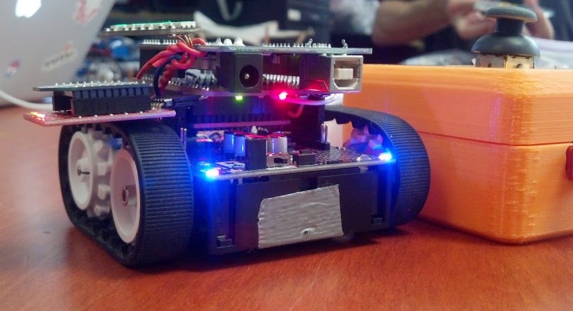
The second robot covered by todays post is Quins White House NFC robot. Quin is a 13 year old active maker from southern California who has his own website, call Qtechknow. Hackaday covered Quins robot that he built and took to the recent White House Maker Faire. The robot appears to be an upgraded version of Quins FuzzBot featured on Instructables. The Hackaday article describes the Pololu-chassis robot this way:
Top view of Quins robot and the controller
"This remote controlled, Arduino-based robot was created by a young student named [Quin] who likes to teach electronics classes at hackerspaces...The quick, little device uses a robot chassis kit with an XBee wireless module so that the controller and the robot can be connected together. An NFC Shield was hacked and split in half so that the wires could be soldered in place. [Quin]‘s goal was to develop a fun game that records the number of times the robot drives over NFC tags laid across a flat surface...The controller container was made with an open source 3D printer called a Bukobot. The enclosure holds an Arduino and another XBee shield along with a joystick and a neopixel ring, giving it a nice polished look complete with a circle of beautiful, flashing LED’s."
The other two robots Ive covered in the blog so far are the Hummingbird Duo and the PopPet. You can buy the Hummingbird Duo kit from Adafruit for $199 plus shipping. The PopPet will cost $80 AUD for the basic kit plus $15 AUD for shipping to the US, or $100 AUD for the advanced kit plus $15 AUD shipping.

So now the question is, who else is interested in building one or several microcontroller-based robots, and which one should we build. This question is one of the ones I plan to ask of participants at this Thursdays Humboldt Microcontrollers Group meeting. If youre interested in robots, please plan to participate in the meeting!

**********
Read More..