Pages

Tampilkan postingan dengan label using. Tampilkan semua postingan

Jumat, 20 Mei 2016

Energia Using The EEPROM on TI Stellaris and Tiva C Launchpads

[Tonights post is by Ed Smith, participant in the Humboldt Microcontrollers Group]

Im writing this blog post largely because it took me quite a while to figure out how to use the Tiva-Cs EEPROM in an effective way. My hope is that this page will make life easier for future people who use the Tiva-C.

First up, these are the Microcontroller boards were going to be talking about today.


The Stellaris LM4F120 / Tiva-C TM4C123 Launchpad and the very snazzy TM4C129 Connected IoT Launchpad.

There are plenty of other Launchpads worth talking about, but all of them fall into one or more of two categories: Launchpads I do not have, and: Launchpads containing no EEPROM.
Not having EEPROM makes this article about using the built in EEPROM a bit irrelevant, and if I havent used it I dont like writing about it.

Many programs and projects dont need to use EEPROM. All the variables are either burnt into the flash and never change, or are kept in RAM and updated as needed for that boot. When power is cycled the program starts fresh and off it goes. You dont need your calculator to remember what you did last week for instance.
There are other times when having some storage is extremely useful, calibrating sensors is a wonderful example. The Humboldt Laser Harp for instance uses EEPROM to store the calibration data for the laser sensors, as well as to store the MIDI "Velocity" of the notes. Without EEPROM you would have to either redo the mechanical/physical calibration every time you turned the harp on in slightly different circumstances (which takes 10-15 minutes), or recompile and reupload the firmware every time.
Almost any sort of sensor that requires calibration once in a while is a good use for EEPROM. Things like odometers or hour meters as well.
That brings us to the question of how.

How do I get access to the EEPROM of my microcontroller?
Im glad you asked!
If youre using an Arduino, or a TI Launchpad and the Energia IDE, the process is very simple.
First you include the EEPROM library (At the top of your program, add "#include <EEPROM.h>" without the quotes), then in your program you call EEPROM.read(address) and EEPROM.write(address, value) to read and store values respectively. For example:

This would read the value at address 10 into the someVariable variable, update it, and then stuff it back into EEPROM address 10.
The process is very simple, if your value fits into a single byte. That is to say, 0-255. If your value is 256 it will be stored as 0. If its 260 it will be stored as 4, and so on.
You have to do some bitshifting to split larger variables up into bytes and store the bytes individually, then bitshift it back together when you want to use it. Its very doable, but something of a pain.
There are add-on Arduino libraries that can be used to automate the bitshifting, though I have not used them.
What I have used is a slightly lower level method of EEPROM access on the TI Stellaris and Tiva-C chips.
This method and example still uses the Energia IDE, though I believe the code is more or less the same for TivaWare and the TI Code Composer Studio.

Instead of EEPROM.whatever, you use "ROM_EEPROMRead(variable, start address, length)" and "ROM_EEPROMProgram(variable, start address, length)".

The trick is, the variables you use are long integers (32 bits, 4 bytes) in an array, rather than single bytes.
The same operation as above, but with the ability to count from zero to a bit over four billion. Quite the improvement over 0-255.

You can also use sizeof(someVariable) rather than listing the number of bytes (so ROM_EEPROMRead(someVariable,10,sizeof(someVariable)); instead of 4) this is useful if youre using an array with more than one variable in it.
What I really like about this method is you can stick an entire array in just as easily, rather than the single member array we declared above you can declare an arbitrarily long array. Say 30 members. Then the exact same ROM_EEPROM calls store that entire array.
It does start to get tricky if youre using a number of addresses, the above example code uses address 10 as its starting point, it also uses address 11, 12 and 13, as the address is done by the number of bytes used. That 30 memory long array would use 120 bytes / address slots.
If you arent paying attention and write something else to the middle of that range youre going to be unhappy with the results!
You get 32kB worth on the basic Tiva-C, and 256kB on the Connected Tiva-C, so you can afford to be lavish.
The really entertaining part to me is that if you use the Arduino style EEPROM calls on the TI chips, the EEPROM library is converting them into the unsigned long flavor of call to interface with the TI MCU itself. That means that if youre storing an unsigned long using the Arduino method on TI chips, youre bitshifting it manually into bytes, then the library is bitshifting it back into unsigned longs and storing it. Bit of a crackup if you ask me.

When you do use EEPROM it is a good idea to think about how often it will be written to, if you write to it once per second you only get 27 hours of operation before you hit the rated lifespan. Real world testing of Arduino (Atmega328 MCU) EEPROM has shown it to typically get to well over 1,000,000 writes before it starts throwing errors. Atmel and TI are not willing to guarantee that youll get a million writes though.
Reads are free, read the EEPROM as often as you want, but try to keep the writes within reason. If you write once per minute youll get ~69 days of operation per the spec, or 694 days if your EEPROM does the >1 million writes many seem to. Once an hour on average gives you a very long lifespan indeed, a bit over 4,000 days per spec or 40,000 if youre lucky. Thats 11 to 110 years, which should be enough.

If you made it this far through this wall of text, congratulations! My next post will have more pictures.
I hope this was an interesting read and/or helped, look for a blog post about the Humboldt Laser Harp coming in the near future. This coming blog post will include some (most? all?) of the code for the laser harp, including the EEPROM bits.

--Ed Smith

**********
Read More..

Minggu, 08 Mei 2016

Using Arduino For Mind Control

This isnt a post about using a microcontroller (MCU) to control someones mind -- its a post about how to use an Arduino device that lets you use your brainwaves to manipulate inanimate objects.
OpenBCI prototype called "Frankenboard"

Heres how the August 11 article "Building Mind-Controlled Gadgets Just Got Easier" from IEEE.org explains this new brain-computer interface (BCI).
"Their system enables DIYers to use brain waves to control anything they can hack—a video game, a robot, you name it. “It feels like there’s going to be a surge,” says Russomanno. “The floodgates are about to open.” And since their technology is open source, the creators hope hackers will also help improve the BCI itself. Their OpenBCI system makes sense of an electroencephalograph (EEG), signal, a general measure of electrical activity in the brain captured via electrodes on the scalp. The fundamental hardware component is a relatively new chip from Texas Instruments, which takes in analog data from up to eight electrodes and converts it to a digital signal. Russomanno and Murphy used the chip and an Arduino board to create OpenBCI, which essentially amplifies the brain signal and sends it via Bluetooth to a computer for processing."
Current OpenBCI board
One nice aspect of Arduino is that its getting more and more people who arent electronics experts, computer programmers or engineers involved with physical computing. The IEEE article says they are "artists who met at Parsons the New School for Design." In the Humboldt Microcontrollers Group, there is a forester, a biologist, and an artist. And wed love to have more non-engineers and others whose main experience and training is not in the field of electronics. The Arduino movement seems to encourage a whole new spectrum of people to see how they can apply MCUs and other modern electronics to their particular field of interest.

I havent quite figured out if I think OpenBCI will be around for the foreseeable future. They seem relatively legitimate, but their website appears to be either very new or not a high priority for the founders of OpenBCI. Quite a few of the webpages on the site say Under Construction. Even the Getting Started page says its under construction. But IEEE is a pretty reputable organization, and I dont think theyd have published the article if they werent comfortable that the project was legitimate. Overall, though, it appears youll get the OpenBCI hardware if you want to spend the $399 on either the 8-bit or 32-bit board kits. They also have a GitHub site that contains "the core OpenBCI hardware and software frameworks."

In addition to the IEEE August 2014 article about OpenBCI, there were a number of articles in early 2014 when OpenBCI did a successful Kickstarter campaign, getting more than twice their original goal of $100,000. Wired did an article in January 2014 titled, "These Guys Are Creating a Brain Scanner You Can Print Out at Home." The article featured a 3D printed brain scanner headset that they called the Spider Claw 3000. Heres the articles description of the brain scanner:
"Spider Claw 3000" 3D printed brain scanner
"It includes sensors and a mini-computer that plugs into sensors on a black skull-grabbing piece of plastic called the “Spider Claw 3000,” which you print out on a 3-D printer. Put it all together, and it operates as a low-cost electroencephalography (EEG) brainwave scanner that connects to your PC...You can target up to 64 locations on the scalp with a maximum of 16 electrodes at a time."
The $399 starting price for the OpenBCI is too steep for my budget, but Im sure there will be some pretty interesting developments with this equipment in the next few years. The IEEE article mentions three projects:
"Audette, the engineer from Creare, is already hacking robotic “battle spiders” that are typically steered by remote control. Audette used an OpenBCI prototype to identify three distinct brain-wave patterns that he can reproduce at will, and he sent those signals to a battle spider to command it to turn left or right or to walk straight ahead. “The first time you get something to move with your brain, the satisfaction is pretty amazing,” Audette says...In Los Angeles, a group is using another prototype to give a paralyzed graffiti artist the ability to practice his craft
Chip Audette and brain-controlled Hex Bug battle spider (from IEEE)
again. The artist, Tempt One, was diagnosed with Lou Gehrig’s disease in 2003 and gradually progressed to the nightmarish “locked in” state. By 2010 he couldn’t move or speak and lay inert in a hospital bed—but with unimpaired consciousness, intellect, and creativity trapped inside his skull...They’re using OpenBCI to record the artist’s brain waves and are devising ways to use those brain waves to control the computer cursor so Tempt can sketch his designs on the screen...David Putrino, director of telemedicine and virtual rehabilitation at the Burke Rehabilitation Center, in White Plains, N.Y., says he’s comparing the open-source system to the $60,000 clinic-grade EEG devices he typically works with...Putrino hopes to use OpenBCI to build a low-cost EEG system that patients can take home from the hospital, and he imagines a host of applications. Stroke patients, for example, could use it to determine when their brains are most receptive to physical therapy, and Parkinson’s patients could use it to find the optimal time to take their medications
."
I wonder what some imaginative teenagers who have a lot of time and energy on their hands will come up when they start hacking OpenBCI...

**********
Read More..

Minggu, 27 Maret 2016

Makeblock YAAR!!

No, Makeblock is not a pirate microcontroller -- its yet another Arduino robot.
Makeblock Gold starter kit

The August 13 Tech In Asia article "This Chinese startup lets kids easily make and program their own robots" is sort of an update of one of the Arduino robot companies thats been around for a while. Theyre a Shenzhen company that did a very successful Kickstarter, ending up with over six times their original $30,000 funding goal. According to the Tech In Asia article:
"...Makeblock, a startup from Shenzhen, offers a cheaper, more practical approach. The company sells robotics kits for as little as US$120 and enterprise kits for up to US$500. Makeblock makes 200 different mechanical parts and growing, which can be programmed using either Arduino or Scratch – the latter is an MIT-developed drag-and-drop programming environment for kids to learn the fundamentals of coding. CEO Jasen Wang says kids can easily make their own toy robots, while more serious hobbyists and even professionals can create robots to be used for more practical applications. Once a robot is built, it can be controlled via mobile app..."
A Wired article from 2012 titled "Robotics Hacker Erects Open Source ‘Lego for Adults’" gives some of the backstory about Makeblock:
"Jasen Wang once bought a home robotics kit. He had studied aircraft design in college and spent years at an electrics engineering outfit, but he still found the instructions completely incomprehensible. And the pieces were flimsy. And after he broke two of them, he gave up entirely. The good news is that he resolved to create his own robotics kit that was actually worthy of the name. The result is Makeblock, a set of flexible components — including slots, wheels, timing belts, and motors — for building robotics...You can even integrate these components with Lego blocks, as well as open source Arduino circuit boards and various other motors and standard industrial parts. And all of Makeblock’s schematics are open source, meaning anyone can build compatible parts or try to improve upon the designs...the company has built a custom-designed servo because Wangs says the ones already on the market weren’t adequate for robotics. And he’s not entirely happy with the existing integration system, so the company is building a new electronic platform that uses modular, color-coded connectors to make it easier to attach circuit boards and sensors...The key to Makeblock’s combination of sturdiness and flexibility are the threaded slots made from aluminum. Wang hit upon the idea at his day job. Although he knew he wanted to build a better robotics kit, he had no idea how. One day, he was asked to learn more more about the production side of the business, so he was sent to the factory to be trained in assembly work. It was here that he came across an aluminum part with a threaded slot, enabling engineers to add screws or connectors anywhere on each piece."
A more recent 2013 article from Make magazine gives Makeblock kudos for the high quality
High quality aluminum parts
parts.
"Compared to t-slot aluminum beams, Makeblock is much more sophisticated. It has threaded grooves running along the length of the beams, bolt holes running parallel to the grooves, as well as threaded holes on the ends of the beams. You can really get a sense of these features in the photo to the right. While the beams are great, Makeblock has created an impressive array of additional parts. The wheels and treads are extremely robust. There’s a nice variety of connector plates."
The electronics kit for Arduino and Scratch is $99 and looks like a pretty good package (its just the electronics).
Electronics kit for Scratch and Arduino

It looks like Makeblock would be an excellent starting point for a person who wants to just build a robust robot and doesnt feel the need to cut and shape every part by hand. I dont think you have to worry about your Makeblock robot falling apart because you didnt cut components to just the right dimensions or werent an expert with a CNC router or a laser cutter.

Maybe Ill ask for a Makeblock kit for Christmas!

**********

Read More..

Jumat, 25 Maret 2016

Pi Bot And Quins White House NFC Robot

Two Arduino-compatible robots are the topic of this post; the Pi-Bot and Quins White House NFC robot.

The Pi-Bot was launched via a Kickstarter campaign which successfully funded on April 10, 2014. The creators of this low-cost robot had a goal of $70,000 and they ended up getting $113,175. The Pi-Bot Kickstarter page explains the robot this way:
Pi-Bot robot
"The Pi-Bot is a uniquely designed (and affordable!) complete robot kit for anyone interested in building and programming robots!...We have developed the perfect hands-on learning platform for both students and professional engineers to learn the hardware and software of robotics...Our team has spent years testing all of the leading robotics kits on the market today. Although many have impressive features, they are either too complicated or overly simplistic... and always much too expensive. Today, a typical Arduino based robot usually costs over $150. Too often we spent money on kits that could not do much or were too costly to be practical. Not to mention, many of these kits used proprietary components that limited the scope of real-world usage. We wanted to change this...Modular platform for interchangeable sensors...Standardized Arduino C programming...We give you the flexibility to design your own projects with included line following and ultrasonic distance sensors. The modular chassis allows sensors to be moved and positioned for your convenience. No soldering is needed to fully construct your Pi-Bot! We are currently developing an assortment of new sensors and motors for even more capabilities in the future."
On their company website, the Pi-Bot creators have video tutorials for building the robot, downloadable chapters of the operating manual and code for the Pi-Bot.

If you want to buy this robot, you can do that from the Pi-Bot website order page. The current cost is $75 plus shipping, handling and taxes. Seems like a pretty reasonable cost.
Quins White House NFC robot

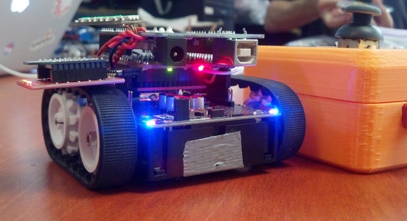
The second robot covered by todays post is Quins White House NFC robot. Quin is a 13 year old active maker from southern California who has his own website, call Qtechknow. Hackaday covered Quins robot that he built and took to the recent White House Maker Faire. The robot appears to be an upgraded version of Quins FuzzBot featured on Instructables. The Hackaday article describes the Pololu-chassis robot this way:
Top view of Quins robot and the controller
"This remote controlled, Arduino-based robot was created by a young student named [Quin] who likes to teach electronics classes at hackerspaces...The quick, little device uses a robot chassis kit with an XBee wireless module so that the controller and the robot can be connected together. An NFC Shield was hacked and split in half so that the wires could be soldered in place. [Quin]‘s goal was to develop a fun game that records the number of times the robot drives over NFC tags laid across a flat surface...The controller container was made with an open source 3D printer called a Bukobot. The enclosure holds an Arduino and another XBee shield along with a joystick and a neopixel ring, giving it a nice polished look complete with a circle of beautiful, flashing LED’s."
The other two robots Ive covered in the blog so far are the Hummingbird Duo and the PopPet. You can buy the Hummingbird Duo kit from Adafruit for $199 plus shipping. The PopPet will cost $80 AUD for the basic kit plus $15 AUD for shipping to the US, or $100 AUD for the advanced kit plus $15 AUD shipping.

So now the question is, who else is interested in building one or several microcontroller-based robots, and which one should we build. This question is one of the ones I plan to ask of participants at this Thursdays Humboldt Microcontrollers Group meeting. If youre interested in robots, please plan to participate in the meeting!

**********
Read More..